| Exam Name: | Implementing and Administering Cisco Solutions (200-301 CCNA) v1.1 | ||
| Exam Code: | 200-301 Dumps | ||
| Vendor: | Cisco | Certification: | CCNA |
| Questions: | 1257 Q&A's | Shared By: | beauden |
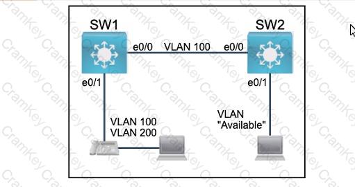
All physical cabling between the two switches is installed. Configure the network connectivity between the switches using the designated VLANs and interfaces.
1. Configure VLAN 100 named Compute and VLAN 200 named Telephony where required for each task.
2. Configure Ethernet0/1 on SW2 to use the existing VLAN named Available.
3. Configure the connection between the switches using access ports.
4. Configure Ethernet0/1 on SW1 using data and voice VLANs.
5. Configure Ethemet0/1 on SW2 so that the Cisco proprietary neighbor discovery protocol is turned off for the designated interface only.
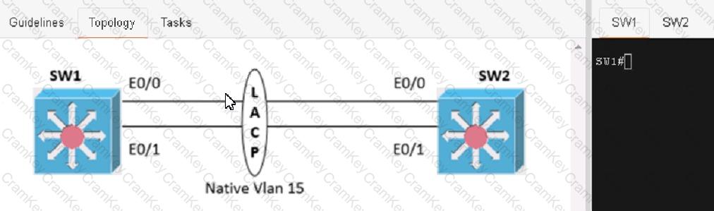
Physical connectivity is implemented between the two Layer 2 switches, and the network connectivity between them must be configured
1. Configure an LACP EtherChannel and number it as 1; configure it between switches SW1 and SVV2 using interfaces Ethernet0/0 and Ethernet0/1 on both sides. The LACP mode must match on both ends
2 Configure the EtherChannel as a trunk link.
3. Configure the trunk link with 802.1 q tags.
4. Configure the native VLAN of the EtherChannel as VLAN 15.
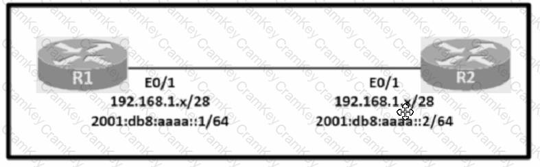
Configure IPv4 and IPv6 connectivity between two routers. For IPv4, use a /28 network from the 192.168.1.0/24 private range. For IPv6, use the first /64 subnet from the 2001:0db8:aaaa::/48 subnet.
1. Using Ethernet0/1 on routers R1 and R2, configure the next usable/28 from the 192.168.1.0/24 range. The network 192.168.1.0/28 is unavailable.
2. For the IPv4 /28 subnet, router R1 must be configured with the first usable host address.
3. For the IPv4 /28 subnet, router R2 must be configured with the last usable host address.
4. For the IPv6 /64 subnet, configure the routers with the IP addressing provided from the topology.
5. A ping must work between the routers on the IPv4 and IPv6 address ranges.
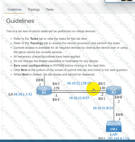
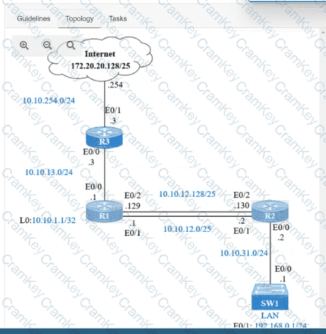
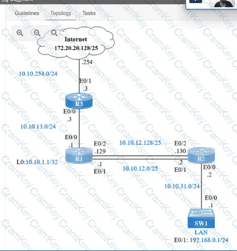
IP connectivity and OSPF are preconfigured on all devices where necessary. Do not make any changes to the IP addressing or OSPF. The company policy uses connected interfaces and next hops when configuring static routes except for load balancing or redundancy without floating static. Connectivity must be established between subnet 172.20.20.128/25 on the Internet and the LAN at 192.168.0.0/24 connected to SW1:
1. Configure reachability to the switch SW1 LAN subnet in router R2.
2. Configure default reachability to the Internet subnet in router R1.
3. Configure a single static route in router R2 to reach to the Internet subnet considering both redundant links between routers R1 and R2. A default route is NOT allowed in router R2.
4. Configure a static route in router R1 toward the switch SW1 LAN subnet where the primary link must be through Ethernet0/1. and the backup link must be through Ethernet0/2 using a floating route. Use the minimal administrative distance value when required.

TESTED 26 Sep 2026